
Line Follower Robot LFR Using 8051
Microcontroller


Line
Follower Robots are very familiar among robot enthusiasts and builders since
almost everyone starts their journey with this simple project. And do not judge
with their simplicity, this kinda robot proves extremely useful in industries,
machinery and much. This article will guide you to build your first line
follower robot using 8051 family Atmel AT89S52 Microcontroller
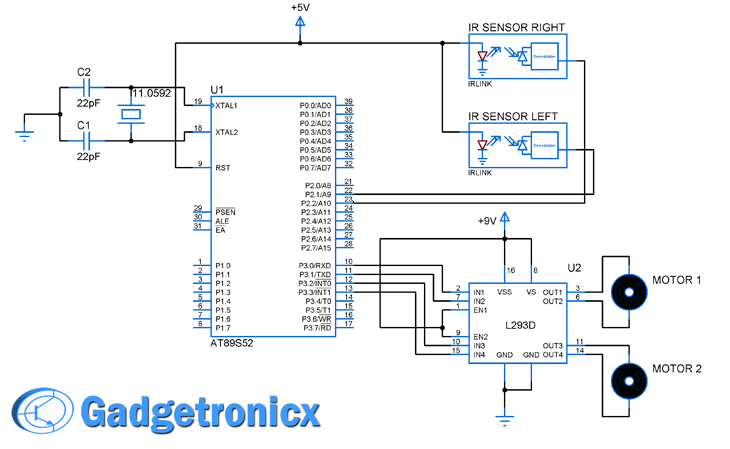
Schematic Design of Line Follower
Robot:
This LFR uses two simple Infra red sensors comprising a IR led and a photodiode to detect the track laid on the surface. Since the black color is a great reflector of the IR beam it reflects back the beam to the diode and in turn it senses it. Do note that this LFR logic works only on black track laid on a white surface.


Thus
the logic for developing the code will be Right sensor hits the black track or
giving logic low, turns Right. Left sensors hits the black track or giving
logic low, turn left. Both sensors are in white floor go straight.
Requirements:
·
Robot Chassis
·
Geared DC Motors
·
Caster wheels
·
Robot Wheels
·
IR Sensor Cards (2 IR sensor module)
·
IC L293D (Driver IC)
·
IC AT89S52 (8051 family)
#include<reg52.h>
sbit
s1=P2^1;// sensor right
sbit
s2=P2^2; // sensor left
sbit
motor_pin_1 = P3^0; // connect motor pins to port 3
sbit
motor_pin_2 = P3^1;
sbit
motor_pin_3 = P3^2;
sbit
motor_pin_4 = P3^3;
void
main ()
{
s1=0;
s2=0;
P3=0x00;
//set Port 3 to low
while(1)
//infinte loop
{
if((s1==0)&(s2==0))
//check sensor is high or not
{
//
forward function
motor_pin_1
= 1;
motor_pin_2
= 0;
motor_pin_3
= 1;
motor_pin_4
= 0;
}
else
if((s1==0)&(s2==1))
{
motor_pin_1
= 1;
motor_pin_2
= 0;
motor_pin_3
= 0;
motor_pin_4
= 0;
}
else
if((s1==1)&(s2==0))
{
motor_pin_1
= 0;
motor_pin_2
= 0;
motor_pin_3
= 1;
motor_pin_4
= 0;
}
else
if((s1==1)&(s2==1))
{
motor_pin_1
= 0;
motor_pin_2
= 0;
motor_pin_3
= 0;
motor_pin_4
= 0;
}
}
}

0 comments:
Post a Comment